We offer an extended range of Automatic Samplers and auxiliary equipment, which were originally designed and tested in cooperation with British Petroleum. Offered Sampling solutions comply requirements of the latest revisions of ISO 3171 and relevant API and IP industry standards. Maurer™ products have enjoyed an enviable worldwide reputation for engineering excellence and long term reliability, with instruments first installed over 30 years ago still providing dependable operation today. Today the Maurer™ product range includes cell samplers, insertion samplers, sample receivers and weigh scales.
Features
- High Repeatability of Grab Volume +/-0.5%.
- Construction of sampler internal non-return valve exit passage avoids separation of immiscible constituents, i.e. water in crude oil during the sampling cycle
- No selective water retention ports within sampler cell
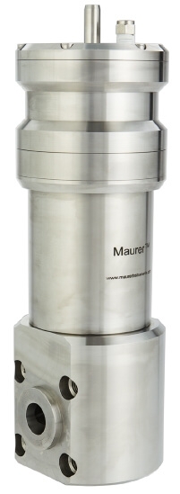
- Stainless steel Construction
- Material selection to meet NACE MR 0715R requirements
- Precision built for precision sampling
- Sampler can be operated at up to 30 grabs/min rate
Purpose
The purpose of a Sampling System is to periodically extract a representative sample from a flowing fluid stream in order to determine its constituent properties. In the case of a two phase fluid stream, the Sampler and the associated collection system must take into account the relative proportions of the immiscible constituents, i.e. water in crude oil, and avoid the 'biasing' of the sample in favor of a particular constituent.
Where dissolved high vapor pressure fractions are also present and these are also subject to determination, the Sample and the associated Sample Collection System must ensure that these fractions are retained during the sampling and storage cycle.
By-pass Sampling
This method of sampling is often preferred for high pressure pipe lines in that the Sampler Cell and its associated flow control equipment can be readily isolated for servicing.
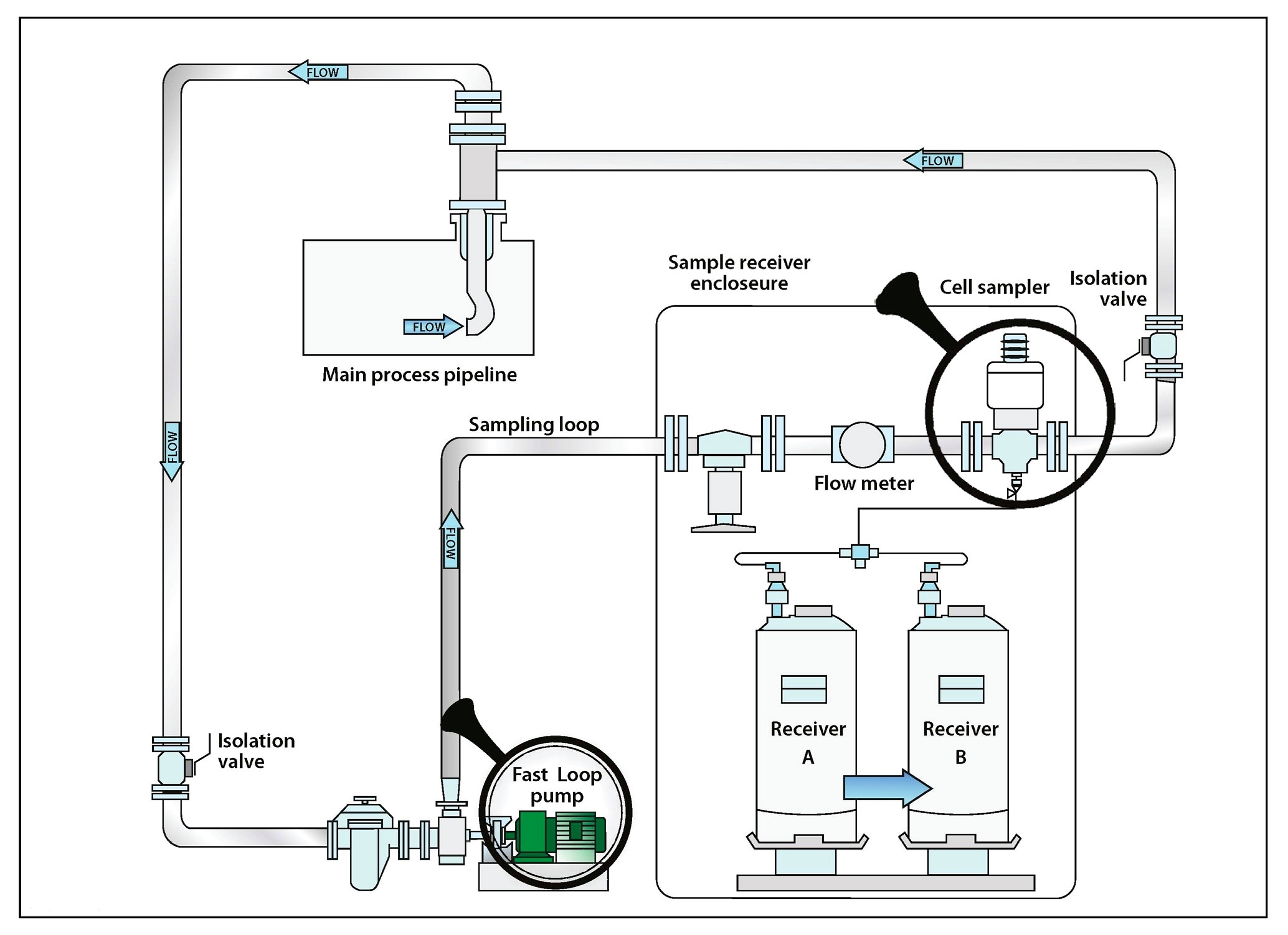
In order to avoid disturbing the relative proportions of any immiscible constituents, i.e. water droplets in crude oil, the flow velocity into the chamfered mouthpiece of the scoop tube should be the same as the average velocity of the bulk fluid, i.e. sampling should be carried out under isokinetic conditions. Thus the scoop tube, pump and, where applicable, the by-pass flow regulating means, should be carefully sized.
For accurate sampling, the fluid entering the scoop tube should be representative of the bulk fluid in the pipe line.
Mode of operation
The downward action of the pneumatically operated piston, releases the capture tube via the 'lost motion’ spring to trap a defined volume of fluid between the non-return valve (N.R.V) assembly and the anvil. The continuing downwards motion of the piston then forces N.R.V. assembly into the trapped fluid thus forcing it to issue under pressure into the Sample Collection System.
The virtue of the lost motion system is that only one set of seals is used in the dynamic mode during the pumping cycle with the added advantage of avoiding water retention points within the sample cell.
A feature of the Maurer Sampler is that the trapped sample is pumped out via a 3mm bore tube and not around the annulus area of the N.R.V. thus avoiding the possibility of water separation within the Sampler itself after capture.
A noticeable feature of the Sampler is that the fluid to be sampled is sectioned upstream of the capture tube via an extended sharp edged pitot tube end flow straightening vane assembly. This system avoids the errors associated with water loss due to 'bluff body’ effects at the Sampler head itself.